

![[]](images/wanddokl.gif)
Design of retaining wall

The conditions under which the
retaining wall must remain stable
(i.e. rough weather and the force
differential caused by the differing
water levels) make exacting demands
on the design. In testing the wall it
was discovered that it began
oscillating uncontrollably under certain
conditions. The wall was for example
sucked downwards by the high velocity
of current below the wall (i.e. a
Venturi effect).
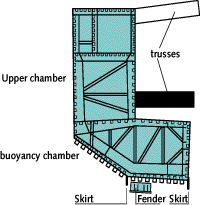
This problem was resolved by
modifying the shape of the wall by
tapering the underside on the seaward
side and by introducing skirts (i.e.
stabilising strips at the outer bottomside
of the retaining wall).
The sections forming the retaining
wall are hollow. This is why the
walls float and can be moved and be
sunk down by letting them fill with water.
The lower buoyancy chambers have
computer-operated valves. The upper
chambers have perforations and
automatically fill with water and
empty again.
The perforations and computer-
operated pumps also help guarantee
the stability of the wall.
There are leaks in the barrier. These
are not however a cause for concern:
the barrier need not keep out all the
water but is a reductor. It proved
simpler to leave a gap of one and a
half metres between the walls to
prevent them from "banging" against
one another in the closed position.
The opening means that water can pass
through the barrier, although this is
made more difficult as a labyrinth of
two steel plates has been
constructed. Water can also pass
beneath the wall, while in a heavy
storm water will also spill over
the top. Water also leaks through the
parking dock. In total these leaks
have a surface area of some 125 m2, or
2.5 percent of the total retaining
surface.
![[overview of retaining wall]](images/wandover.gif)