A Technical Description of the Sensor Chair
Joseph Paradiso
MIT Media Lab
November 7, 1994


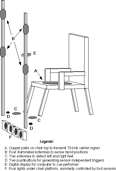
Four receiving antennas (B) are mounted at the verticies of a square, on poles
placed in front of the chair. These pickups receive the transmitted signal
with a strength that is determined by the capacitance between the performer's
body and the sensor antenna. As the seated performer moves his hand forward,
the intensities of these signals are thus a function of the distances between
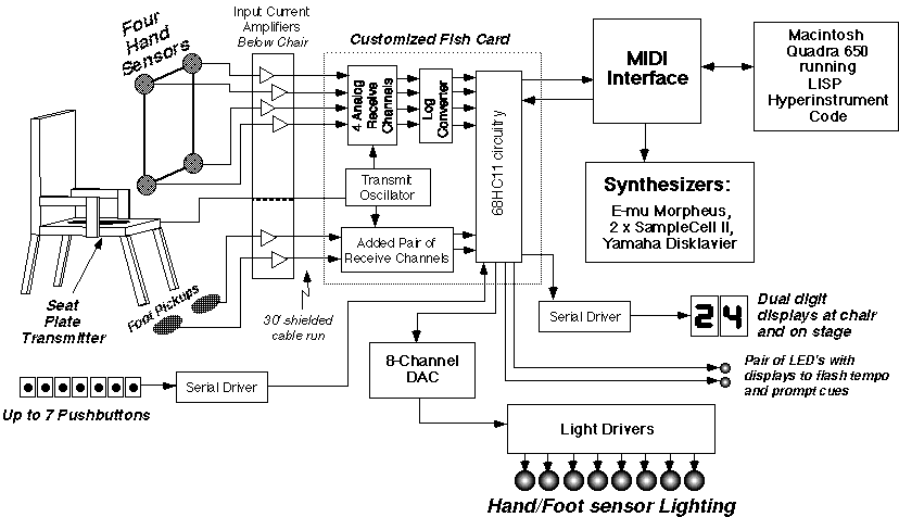
the hand and corresponding pickups. The pickup signal strengths are digitized
and sent to a Macintosh computer, which estimates the hand position. A pair
of pickup antennas are also mounted on the floor of the chair platform, and
are used to similarly measure the proximity of left and right feet, providing
a set of pedal controllers. In order for a performer to use these sensors, he
must be seated in the chair, and thus coupled to the transmitting antenna.
Other performers may also inject signal into the pickup antennas if they are
touching the skin of the seated individual, thus becoming part of the extended
antenna system. The sensor antennas are synchronously demodulated by the
transmitted signal; this produces a receiver tuned precisely to the waveform
broadcast through the performer's body and rejects background from other
sources.
A pair of footswitches (D) are incorporated in this system to provide se
nsor-independent triggers. These are used for changing parameters when the
foot pedals are dedicated to generating musical sounds, or for instigating t
riggers when the performer is not seated, hence is unable to use the sensors.
The hand sensor antennas (B) are composed of a copper mesh encased insid
e a translucent plastic bottle. A halogen bulb is mounted inside this mesh
which is illuminated with a voltage proportional to the detected sensor sign
al (thus is a function of the proximity of the performer's hand to the senso
r), or driven directly by the Macintosh computer as a MIDI light-instrument.
Four lights are mounted below the platform (F); these are correspondingly
driven by the foot-sensor signals or directly through MIDI. A digital displa
y (E) is also mounted on one of the sensor posts; this is similarly defined
as a MIDI device, and is driven by the Macintosh to provide performance cues
(i.e. amount of time or triggers remaining in a particular musical mode, etc
.). The sensors are used to trigger and shape sonic events in several
different ways, depending on the portion of the composition that is being
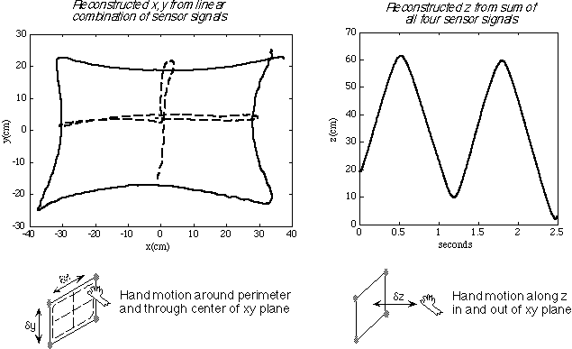
performed. The simplest modes use the proximity of the performer's hand (or
head in the case of Teller's closing bit) to the plane of the hand sensors (z)
to trigger a sound and adjust its volume, while using the position of the hand
in the sensor plane (x,y) to change the timbral characteristics. Other modes
divide the x,y plane into many zones, which contain sounds triggered when the
hand moves into their boundary (i.e. the percussion mode). Several modes
produce audio events that are also sensitive to the velocity of the hands and
feet.
Two additional technical diagrams of the Sensor Chair are shown below:

